Lab 3 - Circuits
In this lab, we’ll get more familiar with combining the logic gates we experienced in class and the reading into more complicated circuits that can do multi-bit calculation. Rather than drawing these circuits on paper, we’ll use a simple digital logic designer, Digital.
Lab Goals
After this lab, you should:
- Understand how to combine logic gates to produce multi-bit operations such as
- The ripple-carry adder
- A subtractor
- Be able to picture how these circuits produce the results of our multi-bit operations
Installing Digital
You need Java installed in your machine to be able to run Digital. We recommend following the instructions from Official Java documentation. If you are stuck, Stack Overflow will be your friend.
If you already have Java installed or if you have successfully installed Java, visit https://github.com/hneemann/Digital?tab=readme-ov-file#download-and-installation and download the *zip file with the executable/JAR/shell script to run Digital on your machine.
Instruction to run Digital is present in https://github.com/hneemann/Digital?tab=readme-ov-file#download-and-installation. Note that you will probably have to invoke digital through the command line on mac or other unix based system. Running java -jar Digital.jar in the directory where you have Digital.jar should open Digital for you.
When you launch Digital for the first time, there is a short getting started guide that will walk you through the tool. PLEASE DON’T SKIP IT.
If you skipped the tutorial unintentionally, you can invoke it at View>Start Tutorial on the menu.
Getting Started
Here is an example that simulates the internals of the D Flip-flop circuit (i.e., the 1-bit register) we discussed in lecture. Don’t worry you are not expected to understand the internals of the D flip flop, use this example as chance to play with simulator to see how it works.
Download the demo file and open it in the digital tool. To simulate your circuit, press the play button below the help on the menu bar. You can see the working of the D Flip flop by toggling the input (D) signal and observing the output (Q) change. The color of the input and output change to a brighter shade of green when the value is 1 (ON). You can right click on C to increase the clock frequency.
We also have a testbench that tests your circuit’s functionality. To run the test bench, click on the play button with a green tick mark on it. The tool should run your circuit against the test cases and show you the input/output from the circuit.
Once you are done experimenting with the demo D Flip-flop, click on File>New to open a new diagram. This will clear the current example circuit and provide you with a blank workspace in which to create.
The tool provides all the logic gates we have discussed in the class so far, along with many other components. For the purpose of this lab, we will only be using the following, available under the Components menu:
- Logic (submenu)
- AND Gate (2)
- OR Gate (3)
- XOR Gate (4)
- Not Gate (1)
- IO (submenu)
- Input
- Output
- Plexers (submenu)
- Multiplexers
Note: For this lab, you should not need to use the NAND or NOR gates, but you are welcome to use them.
Practice drawing a few gates first. Take a look at Digital’s inbuilt tutorial if you have not already.
Below, we can see a simple circuit with 3 inputs and 1 output. The top two inputs (one 1 and one 0) are connected to an XOR gate. Since 1 ^ 0 = 1, we see that result is connected to the first input to the AND gate. Our third input (1) is connected directly to the AND gate as its second input. Lastly, we see that the result of the AND is connected to an output which is in bright green indicating it is 1.
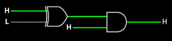
Example Circuit
Once you have become familiar with the tool interface, it is time to try out some of our circuits from class.
Experimenting with Circuits
For the rest of lab, we’ll ask you to load, modify, or draw some circuits and then test them with a few inputs. The goal here is to understand more fully how the logic gates in our circuits combine to produce the answers we expect, so we will be asking you to experiment with them rather than directly calculate the final results as we might have with Homework 1.
Note: Our Autograder requires specific input/output component names and is case-sensitive. The required IO component names will be specified in each section. Please make sure your circuits adhere to the naming requirement.
Ripple Carry Adder
Signal name requirement : Do not modify the names of the IO components have in the starter file.
Begin by loading the 4-bit Ripple Carry Adder that computes X = A + B, as discussed in the Fancier Logic reading and in class. Download Starter File - ripple-carry-adder.dig, then choose File and Open File in the simulator. It should draw the ripple carry adder as seen below.
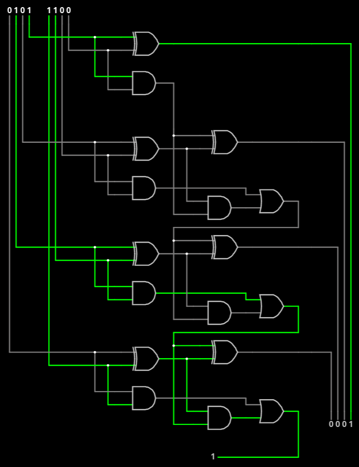
Ripple Carry Adder in Simulator adding 5 + 12 with overflow (or 5 + -4 in two’s complement)
Note : The testbench provided with the starter file is intended to test a 5-bit adder. It will throw an error if you test on a 4-bit adder.
We have collected the input wires in the upper left (4 bits for A and 4 bits for B), and the four output wires in the bottom right (4 bits for X). At the very bottom, you’ll notice the carry bit, which does not form part of the output for X. Clicking on an input bit’s value will change its value from 0 to 1 when the simulator is running.
Run the simulation and add the following numbers (given in decimal):
- 0 + 1
- 1 + 1
- 2 + 2
- 10 + 5
- 15 + 1
- 15 + 15
Note the output in each case and how any overflow is (or is not) handled in the circuit.
Now modify the adder to add 5-bit numbers instead. You could selact and copy-paste a section of the circuit diagram.
Run the simulation again and add the following numbers (given in decimal):
- 0 + 1
- 15 + 1
- 16 + 15
- 31 + 1
- 31 + 31
Save your circuit by using the File, Save As menu. Do not share this with others outside your lab group, but save a copy to check off with your TA.
Ripple Carry Subtractor
Signal name requirement : Same as the ripple-carry-adder circuit.
We are providing you with a starter file which contains a 4-bit adder circuit.
Starter File : subtractor.dig
Note : The testbench provided with the starter file is intended to test a 5-bit subtractor. It will throw an error if you test on a 4-bit subtractor.
Now, modify the 4-bit ripple carry adder in the starter file to produce a subtractor instead. Since your adder originally calculated X = A + B, it should now produce X = A - B. Brainstorm some different ideas converting your adder into a subtractor.
- What is the fewest number of gates you need to add in order to produce a subtractor?
- You may want to “pre-process” one of your 5-bit inputs
- You may need an additional input bit
Note: Use Components>Wires>Supply Voltage to force an input to be 1.
Note: Use Components>Wires>Ground to force an input to be 0.
Once you have created your subtractor, run your simulation and subtract the following numbers (given in decimal):
- 15 - 0
- 15 - 1
- 31 - 31
- 22 - 6
- 22 - 3
- 6 - 19
- 0 - 1
Note the output in each case and what happens when the result would be negative. How does this help us with Two’s Complement? (Remember that 11111 is -1 in 5-bit Two’s Complement.)
Save your circuit by using the File, Save As menu. Make sure you are not overwriting the ripple-carry-adder file. Do not share this with others outside your lab group, but save a copy to check off with your TA.
Towards a Computer ( A mini ALU )
Please download the following starter file and open it in the tool.
Signal name requirement : Input : CC - icode (2 bits) Input : A - input value (1 bit) Input : B - input value (1 bit) Output : X - output result (1 bit)
Next we will create a new circuit.
In class, we have been working towards building a computer that we can program with instructions. We created circuits to handle the work, on Wednesday, we’ll add a mux to choose the resulting value we wanted to store and a register to store the value for the next calculation.
For the rest of lab today, we will build a simplified version to visualize how the circuits will work. In this simplified version, we will define 4-bit instructions [CCAB] as follows:
- The first two bits (CC) will be the instruction code (that is, the “icode”) that determines what operation we will compute
- The third (A) and fourth (B) bits will be the two input values1
Our simplified circuit will compute a different operation, depending on which icode we provide, and output its result as follows:
| icode | operation |
|---|---|
0 | a AND b |
1 | a OR b |
2 | a XOR b |
3 | NOT a |
In our circuit, these 4-bit instructions enter as 3 separate inputs, two 1-bit inputs and one 2-bit input. For example, if our instruction was 0110, the icode bits are 01 and the operands are 1 and 0; therefore, our circuit would output the result of 1 OR 0, which is 11.
Note: to create a nulti-bit component, right click on the component and change the Data Bits field.
We will build this circuit in 2 parts: one part that handles the icode and another that handles the calculations.
Handling the icodes
To choose which operation’s value to output, we will use a multiplexer. Note that we have 4 icode values, so we must construct a 4-input mux, which requires a 2-bit choice value.
You can select a multiplexer (mux) from the plexers submenu in the components menu. Right click on the mux you created and change the Number of Selector Bits to 2 as our icode is 2-bit wide.
Once completed, you should have 4 wires ready for inputs to be connected to your mux, the final Logic Output connected to the output of your mux, and the first two Logic Inputs of our instruction (the first two input bits) used as the choice.
Performing the operations
Next, we must calculate the operations. We will always calculate all 4 operations; our mux will determine which operation is ultimately output2.
- Draw gates for each of the 4 operations, connecting their output to the respective input of the 4-input mux.
- Draw 2 Logic Inputs that will serve as the last two bits of our 4-bit instruction. Connect them to each logic gate in the previous step, as appropriate.
Testing your circuit
Once you have completed your circuit, try out a few different instructions:
0001- This should AND 0 and 1 (outputting 0)0110- This should OR 1 and 0 (outputting 1)1011- This should XOR 1 and 1 (outputting 0)1101- This should NOT 0 (outputting 1)
Save your circuit by using the File, Save As menu. Do not share this with others outside your lab group, but save a copy to check off with your TA.
Check-off
Upload the following to gradescope:
- Your ripple carry adder ripple-carry-adder.dig
- Your subtractor subtractor.dig
- Your mini ALU that takes opcodes mini-ALU.dig
To check-off this lab, show a TA
- Once you submitted your files check in with TA so that they can give you attendence credit.
- (Optional) Your multi-purpose circuit with the instructions
1010,1110, and0100
-
Note: this is different from our instructions in class to make designing the circuit in the simulator easier. In class, the two operands will tell us from which register to read (or write) the value. ↩ ↩2
-
In class, this output would be routed to the register file to be saved as needed and used in a future calculation. In our simplified circuit, we are not asking you to draw the register. If you wanted to experiment with it after class, the 1-bit D flip-flop register shown in class is available in the Components->->Flip-Flops menu as the D Flip-Flop. (Selecting the circuit will replace your current drawing, but you may then select and copy, then undo and paste to add it to your drawing.) ↩